Bolnes
From the pages of mecmuseum.nl which is now defunkt.

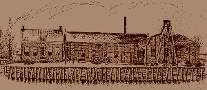
On 13 May 1885, the Board of Mayor and Aldermen of Ridderkerk granted permission to Mr. Johann Hendrik van Cappellen to establish a 'Factory for Steam and other Machines' in Bolnes.
He started with a simple foundry and soon supplied bollards, safes and mooring clamps. The foundry was expanded and a machine factory was added. This was followed by the production of steering gear and hand winches for Rhine lighters and for the yards, punching machines, shears and bending pliers.
Steam engines and steam boilers
In connection with the great progress of Rotterdam in the shipping field, many small and large tugs were built by the shipyards in Rotterdam and on the rivers. On a modest scale, orders were given to the factory in Bolnes for the construction and assembly of steam engines and steam boilers. The first of approximately 100 hp was placed in a ferry for the Municipality of Rotterdam. In total, 144 steam engines with a total capacity of 47794 hp were delivered, the smallest machine was 68 hp, while the largest had a capacity of 1250 hp. 158 steam boilers were manufactured. At the end of the 20th century, the manufacture of steam engines came to a definitive end.
NV Machine Factory Bolnes
Formerly IH van Cappellen CF van Cappellen. In business from 1890-1954. In 1908 the firm was converted into a public limited company, namely NV Machinefabriek Bolnes formerly JH van Cappellen. Johann Hendrik van Cappellen retired from the business and his son Cornelis Willem was appointed director of the new NV.
The first crude oil engine, the hot bulb engine
It was seen early on that the crude oil glow head engine would become a formidable competitor to the steam engine and in 1909 Bolnes decided to build it.
The first engine had a capacity of 30 hp and was equipped with a closed viewing cabinet. The power range was 20 to 600 hp at speeds of 330 to 175 rpm. The fuel consumption was approximately 280 gr/hp/hour.
Starting was done with compressed air of approx. 2atm., while the hot head on the cylinder had to be heated first. The fuel mixture in the cylinder ignited because the injected crude oil was sprayed against the heated head of the cylinder. Hence the name hot head engine. The first Bolnes hot head engine.
In addition to hot head engines, brush machines, tools for sawmills and even mobile vacuum cleaner installations were also manufactured.
The move
The limited space in Bolnes and the ever-increasing demand for machine installations urgently required a larger site and expansion of production possibilities.
In 1910, the decision was made that the future of Bolnes would lie in Krimpen aan de Lek.
In this year, the buildings were purchased and the temporary right of leasehold was obtained from the closed shipyard Rotterdam.
At that time, Machinefabriek Bolnes was located on the river island ' De Zaag' in Krimpen aan de Lek , located opposite the town of Bolnes.
New type of glow head engine with cross head
After a few years of experience with the first hot bulb engines, these machines appeared to suffer a lot from piston wear and overheating engine parts. A type II, an 'open' engine was developed, which solved all the above-mentioned objections. The machine was provided with slideways and the crosshead was introduced. To this day, the crosshead is still used in the Bolnes engines. In total, 433 hot bulb engines with a total capacity of 24,440 hp were built. The last two were delivered in 1935.
1928 The first Diesel engine
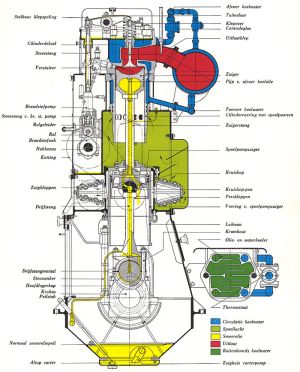
In 1926 Johann Hendrik van Cappellen joined his father in the business. One of his first tasks was to design a diesel engine, based on the experiences with the hot bulb engines. In 1928 the construction of diesel engines was started and at the same time existing hot bulb engines were converted to diesel engines. Originally they were diesel engines with an open front and a speed of maximum 400 rpm.
1932 an improved version came onto the market, the first diesel engine in a closed design with a maximum output of 300 hp at 600 rpm.
The crosshead was designed as a flushing pump; a construction that is still used today.
The welded unit Bolnes diesel engine
In 1948, Mr. IH van Cappellen made a study trip to the United States. He returned with the idea to weld and assemble future engines from simple standard parts.
In collaboration with Prof. Ir. Kroon of the Technical University in Delft, a new engine type was developed with a bore of 190mm and a stroke of 350mm. The power per cylinder was 50 hp at 430 rpm. In 1949, the first tested diesel engine came into production.
The competition

Due to fierce competition from the so-called cheaper countries such as Japan, Korea and Singapore, the Dutch shipbuilding industry and also the Bolnes and other companies got into serious trouble.
And so in the eighties of the twentieth century, the Ridderkerk shipbuilding industry came to an end due to bankruptcies. The engine manufacturer Bolnes was sold in 1987 to the then Stork Wartsila, which then stopped the production of Bolnes engines. Although Bolnes was forced by market conditions to sell its diesel engine division to the Finnish company Wärtsilä in 1987, a large part of the staff was able to continue working at De Zaag until October 1996. Since then, the workshops and offices have been located in Schiedam and Zwolle. Fortunately, there are still shipyards and machine factories that can still supply or replace one or two things. One of them is Olthof on the Nijverheidsstraat, Capelle a/d IJssel.
The welded frame
In 1949 the first welded Bolnes diesel engine went into production. The entire welded frame, which is approximately 50% lighter than a similar cast iron frame, consists of 50 HP sections that are welded together. This finally puts an end to 2, 3, 4, 5, 6, 7, 8, 9 and 10 cylinder casting models and the enormous stocks that have to be maintained to meet the diversity in orders. These sections consist of two boxes per cylinder, between which the frame plates are placed.

Top box
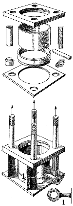
The upper box is called the cylinder, because the chrome cylinder liner for the working piston will be placed in it later. This cylinder consists of several plates and pieces of pipe which are welded together according to the plate next to it. The large bushing in the middle is the cooling water jacket, the cooling water supply comes from below. The four pipe pieces in the corners have welded-on bulkheads lengthwise, the bevelled edges of which at ( l ) will later be welded to the frame plates. The four pipes have threaded bushings at the bottom, in which the four long studs will later be placed to secure the cylinder cover. The very large combustion force on the cover, i.e. on the four studs, is now transferred via welded connections in the longitudinal direction of the force on the frame plate, which is much stronger than in the transverse direction. Patents were obtained on this construction in many countries.
Second box
The second box, which is below the first, is called the purge air box, because the lining in which the crosshead/purge piston runs is placed in this box. This is somewhat simpler in design because there are practically no forces on it. It is also a box that is assembled from various plates and rings by welding. (2 plates below). Both boxes are annealed, pickled, phosphated and then pre-treated.
Now the frame plate.
This is automatically cut out with autogenous gas from 8 mm steel plate approved by the classification societies (All vital material used by 'Bolnes' is approved by these societies, regardless of whether it is ordered or not). A forged steel bearing holder is welded into the recess at the bottom, in which the crankshaft bearing will later be placed. On one side there is another distance pipe with a 1 1/4 ww tension anchor inside. This is a pre-stressed connection that can be removed, making the entire crankshaft very easy to dismantle (the top can remain in place!) (plate next to it). There is also a port P through which all the scavenging air spaces are connected to each other. The cylinders, scavenging air boxes and frame plates are manufactured in large series in ongoing production.
The assembly
If an order is now placed for a six-cylinder frame, for example, six cylinders, six flushing air boxes and seven frame plates are taken. These are taken to one of the welding benches where six vertical mandrels and one horizontal axis are ready. On each vertical mandrel one cylinder and one flushing box are now placed, which are automatically kept at the right distance, while the seven frame plates are screwed to the horizontal axis at the place where the crankshaft will later be. This whole is fitted in the welding bench.
Revolving
This is rotatable to always be able to weld in the easiest way and indeed a few days later the six-cylinder frame is ready!. By this way of clamping along the main axes for welding it is achieved that the shrinkage is extremely small; which is partly due to a precisely determined 'welding recipe'. The drawing of the frame is then only a few tenths of a mm at a length of 3.60 meters; so that the processing allowances can be very small.